Page 1 of 2
Radio Plug for Power Details
Posted: Thu Nov 10, 2016 6:27 pm
by bbolander
I'm using the radio plug behind the passenger seat to power my 24V-12V converter and my CB, Ham and DC outlet for GPS and phone charging.
I received the radio plug today. I've seen posts about being sure which terminal is positive and about tinning the wires. But maybe more detail is needed before I start this.
The plug only goes in one way because of the keyed slot. It needs to be pushed on by hand in order for the threaded nut to engage the existing plug. So I tried doing that and it does not push right in. I think it's going to have to be hammered in or something harder than a regular push. Anyone know the trick to getting the new plug pushed into the existing plug?
The new plug has male pins in it to engage the female holes in the existing plug. So the new power wires are soldered into those male pins. I've heard "tinning". Do you mean tin the wires themselves before you put them in the pins? Then add more solder to fix them into the pins?
There's a plastic sleeve over the flex tubing section where the new wires leave. What is that plastic sleeve for? Maybe for a military wire loom over the radio wires?
Here's a picture of the new plug end where the new wires are to be soldered into the male pins:
- IMG_1158 copy.jpg (252.14 KiB) Viewed 5399 times
Here's a close-up picture of the new plug end where the new wires are to be soldered into the male pins:
- IMG_1159 copy.jpg (170.05 KiB) Viewed 5399 times
Here's a picture of the new plug showing the male pins and keyed slot that will only let the plug go into the existing plug one way:
- IMG_1160 copy.jpg (195.58 KiB) Viewed 5399 times
Here's a picture of the plastic sleeve over the flex where the new wiring will leave the plug:
- IMG_1161 copy.jpg (270.44 KiB) Viewed 5399 times
Re: Radio Plug for Power Details
Posted: Thu Nov 10, 2016 6:49 pm
by bbolander
I partially have answered my first question. The large nut comes quite close to engaging the existing plug. Might need some pushing on still though. It's hard for me to see how threading that large nut on will push the new rubber plug back far enough to fully engage the male pins into the female holes. That rubber plug is hard to move! Still interested in any tricks.
Re: Radio Plug for Power Details
Posted: Thu Nov 10, 2016 8:11 pm
by rmel
At least for the plugs I have, the male pins are not surrounded by a rubber insert.
Rather, there is rubber seal at the inside base of the two protruding male pins -- sealing
the M/F interface after the plugs are mated. This plug doesn't look right to me. Maybe
you can "pluck" that rubber surround out ?
Re: Radio Plug for Power Details
Posted: Thu Nov 10, 2016 8:19 pm
by bbolander
rmel wrote:At least for the plugs I have, the male pins are not surrounded by a rubber insert.
Rather, there is rubber seal at the inside base of the two protruding male pins -- sealing
the M/F interface after the plugs are mated. This plug doesn't look right to me. Maybe
you can "pluck" that rubber surround out ?
Good idea! Haven't thought of that. Interested in other's comments who have had my same plug with the big rubber plug in question.
Re: Radio Plug for Power Details
Posted: Thu Nov 10, 2016 8:51 pm
by rmel
Ah ha!! I just took one of my new unused plugs apart -- got curious.
Yup! That rubber grommet that surrounds the male pins should be
removed, it belongs on the other end where you solder the wires to
the male pins. Then it provides a tight seal when you screw the strain
relief over it.
Re: Radio Plug for Power Details
Posted: Thu Nov 10, 2016 9:02 pm
by bbolander
rmel wrote:Ah ha!! I just took one of my new unused plugs apart -- got curious.
Yup! That rubber grommet that surrounds the male pins should be
removed, it belongs on the other end where you solder the wires to
the male pins. Then it provides a tight seal when you screw the strain
relief over it.
Yep, that's it. Just pulled out the rubber plug from mine easily with needle nosed pliers. Great! Will help others who follow too.
Re: Radio Plug for Power Details
Posted: Thu Nov 10, 2016 9:06 pm
by bbolander
No instructions whatever with the new radio plug. Seems like SAV should write some up to send with it.
Re: Radio Plug for Power Details
Posted: Thu Nov 10, 2016 10:42 pm
by rmel
Now you can get that HAM gear up and running and maybe we can QSO over the Western Reflector ala IRLP

Re: Radio Plug for Power Details
Posted: Fri Nov 11, 2016 9:22 am
by bbolander
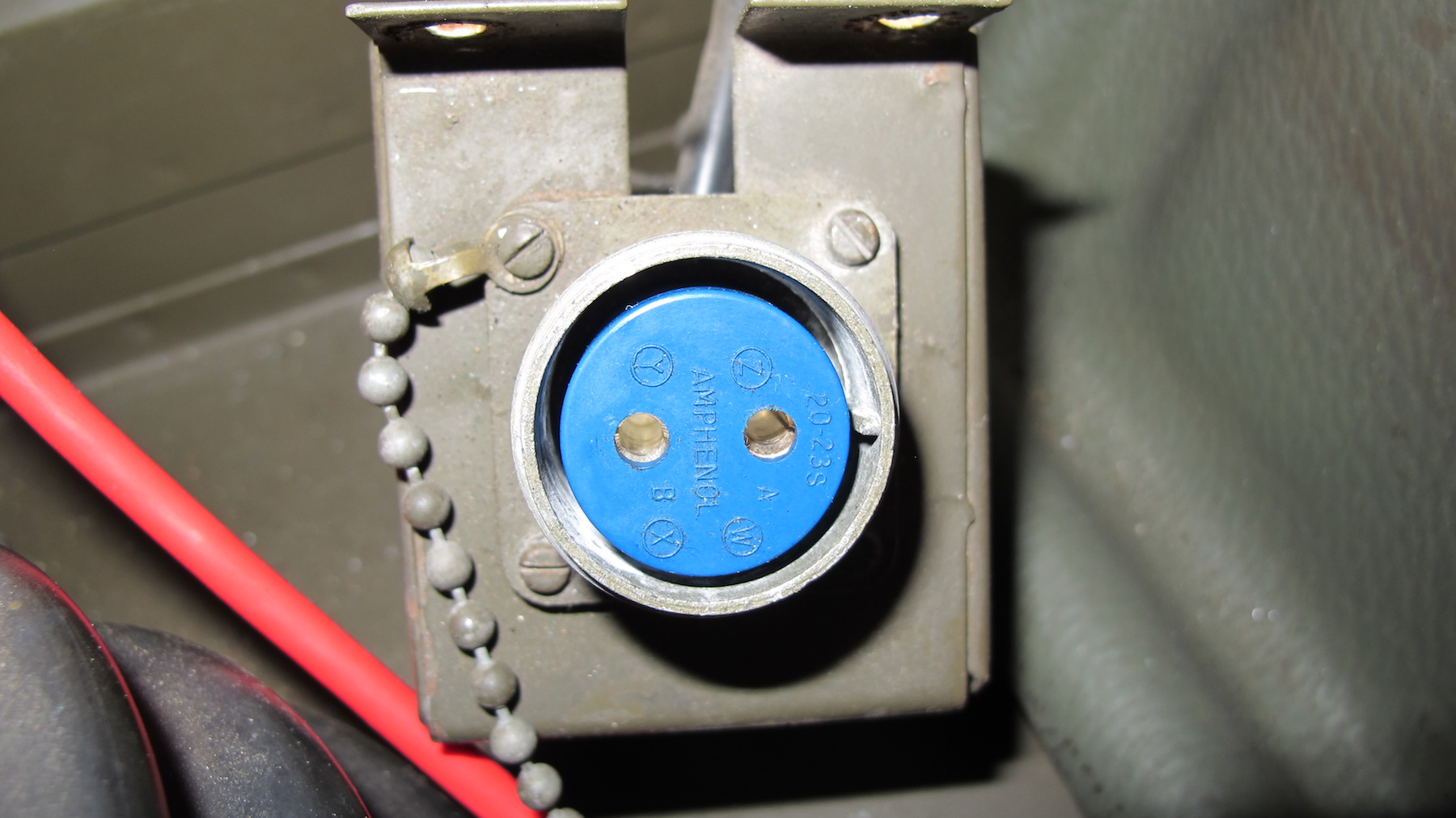
I've heard posts about soldering the new hot wire to A or B on the new radio plug. I've added pictures of mine to show more detail which should be helpful. In my case my new hot wire will be soldered to pin B which is where the hot wire to the existing plug is. In my case pin A is just a simple ground to an existing radio plug mounting screw. All is dictated by the keyed slot in the new piece requiring the new plug to be inserted into the existing one only one way.
Remove the rubber plug insert from the pins in the new plug. It goes on top of where you solder your wires into the pins.
Here are pictures of my existing radio plug clearly showing the keyed slot guide, pins A & B and that my hot wire is on pin B:
- IMG_1165 copy.jpg (343.95 KiB) Viewed 5356 times
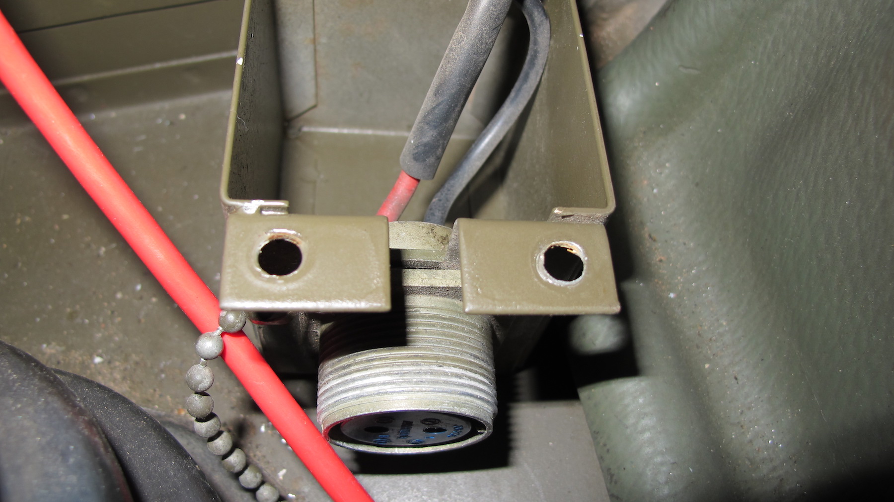
- IMG_1166 copy.jpg (378.84 KiB) Viewed 5356 times
Here are pictures of my new radio plug showing the rubber plug, keyed slot and pins A & B:
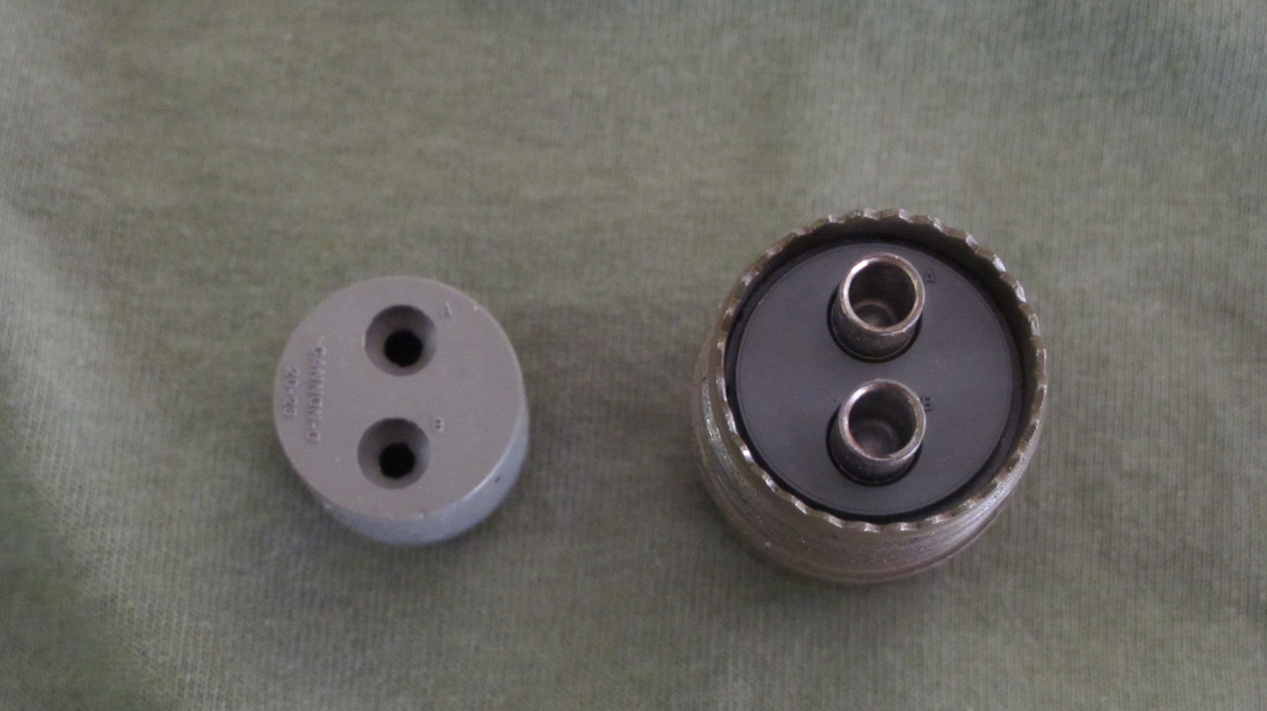
- IMG_1167 copy.jpg (376.17 KiB) Viewed 5356 times
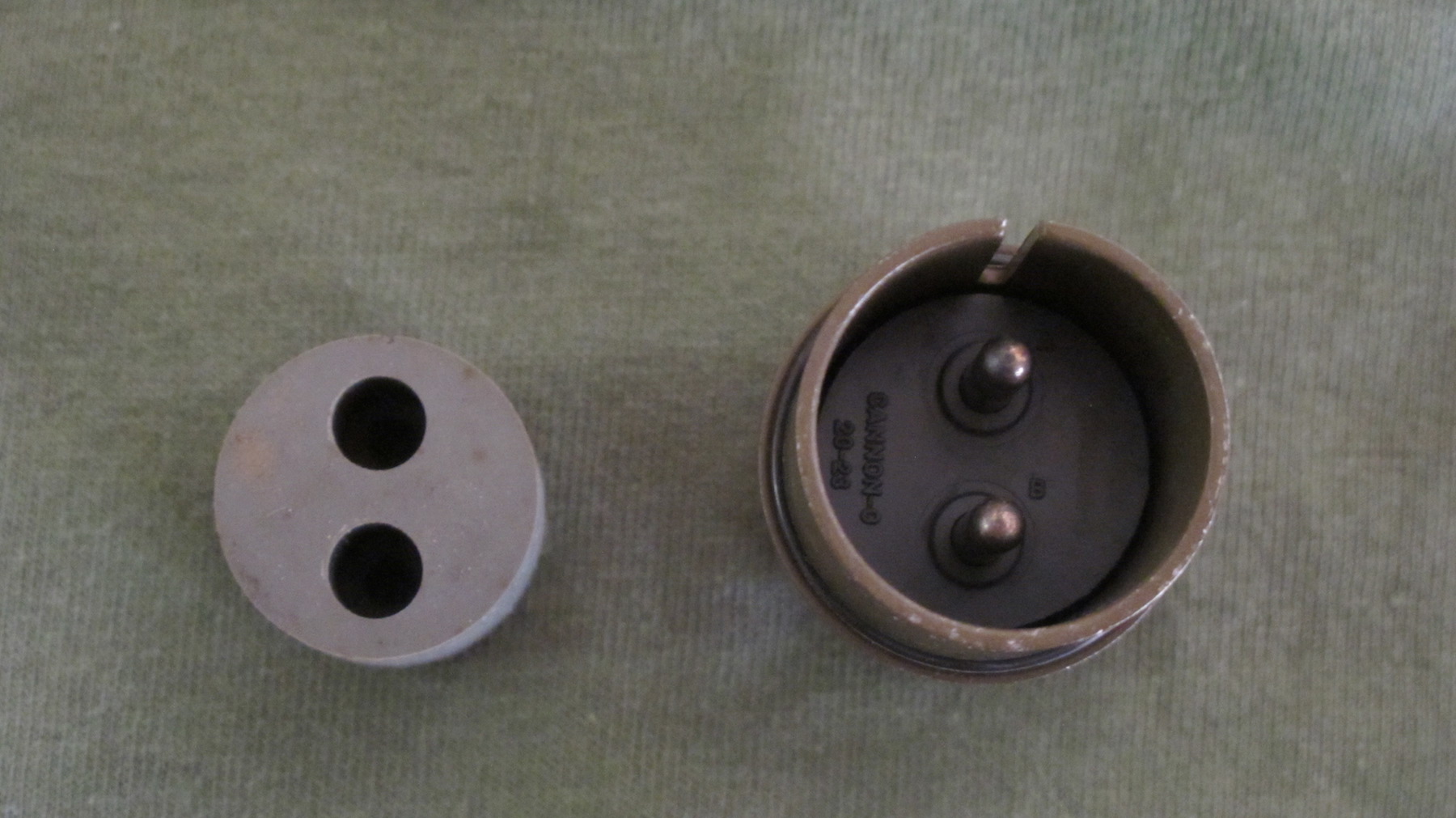
- IMG_1172 copy.jpg (375.27 KiB) Viewed 5356 times
Re: Radio Plug for Power Details
Posted: Fri Nov 11, 2016 10:00 am
by bbolander
Re: Radio Plug for Power Details
Posted: Fri Nov 11, 2016 10:07 am
by bbolander
The last point I'm not clear on is soldering the new wire into the new plug pins. Are you suggesting tinning the wire itself first before putting it into the pin so that it's more solid than the stranded wire? I can also see putting solder into the new pin with the new wire in it, because it isn't a tight connection otherwise. But it will be easy to overfill with solder, preventing a flush closure of the rubber plug to the pin plate. Do you flux the inside of the pin and new wire before soldering?
Any soldering tips would be helpful.
Re: Radio Plug for Power Details
Posted: Fri Nov 11, 2016 11:42 am
by rmel
Beats me, I haven't had the need to solder one of these plugs together yet.
But if I were to do it, I'd use a high wattage iron and a high quality solder with a
flux core. If you can, use wire with high temp insulation, it's going to shrink back
on you no matter what. I would not pre-tin either the wire or pin, the flux will
help facilitate the flow of solder. The rubber insert will protect the pins and exposed
soldered wire that gets exposed.
Re: Radio Plug for Power Details
Posted: Fri Nov 11, 2016 11:48 am
by Jimm391730
The official military soldering specifications require that the strands of the wire be pre-tinned before soldering into the pin pocket. Doing this is just best practice; it has several benefits: The surface of the wire has "new" untarnished solder and the space between all the strands is already filled with solder so you do not have to add as much additional solder when connecting to the pin. You also know that all the strands are more easily heated since they are already bonded with solder.
You should strip the wire so that no more than one wire diameter of bare strands are visible between the end of the insulation and the top edge of the pin pocket. You do not want the insulation to be too close as you need to have an area of wire to add solder to; the iron should be heating the outside of the pin. Do not add an solder to the pin pocket before inserting the wire. Once the pin is hot, begin to add solder at the junction between inside of the pin pocket and the tinned wire. Give time for the wire to heat, then only add enough solder to give a neat meniscus of solder between the top rim of the pin and the tinned wire. Do this in one spot, so the solder can flow in and the excess air can flow out at another location. The Mil Standard says that the strands of the wire should remain visible; do not add so much solder that the strands are obscured from view. Let the solder cool without moving the wire. Then the best practice is to clean the flux away with alcohol (usually with a small brush) and then cover the back of the pin and a short distance up the wire with heat shrink tubing. Of course these is what the Mil Spec strives for; it depends on your skill and experience in soldering, but this is the gold standard to aim for in your soldering.
Re: Radio Plug for Power Details
Posted: Fri Nov 11, 2016 12:18 pm
by bbolander
Jimm391730 wrote:The official military soldering specifications require that the strands of the wire be pre-tinned before soldering into the pin pocket. Doing this is just best practice; it has several benefits: The surface of the wire has "new" untarnished solder and the space between all the strands is already filled with solder so you do not have to add as much additional solder when connecting to the pin. You also know that all the strands are more easily heated since they are already bonded with solder.
You should strip the wire so that no more than one wire diameter of bare strands are visible between the end of the insulation and the top edge of the pin pocket. You do not want the insulation to be too close as you need to have an area of wire to add solder to; the iron should be heating the outside of the pin. Do not add an solder to the pin pocket before inserting the wire. Once the pin is hot, begin to add solder at the junction between inside of the pin pocket and the tinned wire. Give time for the wire to heat, then only add enough solder to give a neat meniscus of solder between the top rim of the pin and the tinned wire. Do this in one spot, so the solder can flow in and the excess air can flow out at another location. The Mil Standard says that the strands of the wire should remain visible; do not add so much solder that the strands are obscured from view. Let the solder cool without moving the wire. Then the best practice is to clean the flux away with alcohol (usually with a small brush) and then cover the back of the pin and a short distance up the wire with heat shrink tubing. Of course these is what the Mil Spec strives for; it depends on your skill and experience in soldering, but this is the gold standard to aim for in your soldering.
Perfect. Exactly what I wanted to know and great for future reference for others. I think this completes a really good detailed thread on using the radio plug for power. I hope my install is up to military standards - I'll soon find out!
I've thought about heat shrink to cover the exposed wire, but in this case that might interfere with installing the rubber plug over the wire and the pin terminals. I know it won't want to pass through the smaller opening at the top of the rubber plug. It might pass through the larger lower portion of the rubber plug and needs to be short to do that. The rubber plug provides insulation so I don't think heat shrink would work here or be necessary. In other applications, yes.
Re: Radio Plug for Power Details
Posted: Sat Nov 12, 2016 7:04 pm
by bbolander
I wanted to finish this with I'm going to use the ground connection at the battery switch rather than the short ground to the screw on the existing radio plug box. The ham radio and CB instructions say to wire the negative wire directly to the battery negative terminal as I've done in other vehicles. In this case though, we don't want to do that because of the battery cut-off switch. I believe from this other thread that my converter negative ground should go to the battery switch ground connection (the one WITHOUT the blue wire).
viewtopic.php?f=14&t=10531&hilit=battery+switch+wiring
Borrowed from the linked thread:
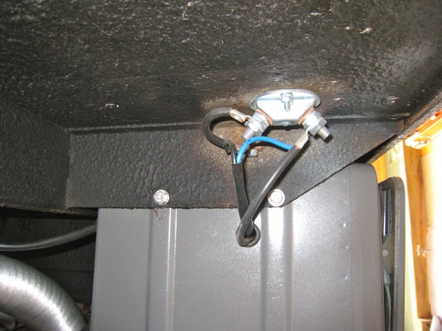
- battery switch IMG_2336.jpg (93.92 KiB) Viewed 5298 times