My spotlight wiring plans

Dedicated to the memory and knowledge shared by Jim Mettler - All things relating to the flow of electrons in a Pinz.
Post Reply
spandit
Posts: 660
Joined: Tue May 18, 2010 5:15 am
Location: East Sussex

My spotlight wiring plans

Post by spandit »

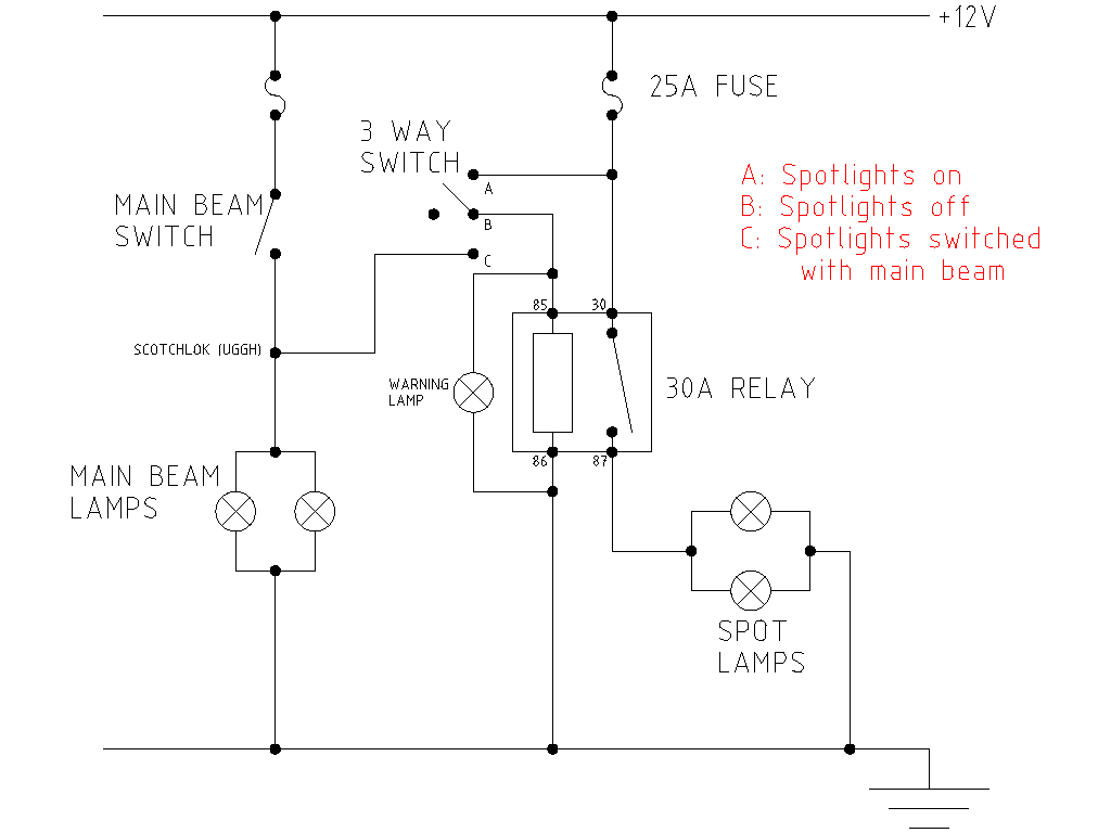
I'm planning on fitting three sets of spotlights onto the Pinzgauer, forward facing, left and right (need the sideways facing ones for some navigational challenges on the Mac4x4). I'm going to mount all the switches/relays etc. in a cubby box with a quick connector should I need to remove it. The side facing lights will be individually switched and the forward facing ones can be either switched on by themselves or with the main beam.

The problems I've had are that the switches I've bought have LEDs in them but are 12V only. The relays I have to hand are also 12V but as discussed in an earlier thread, you can use these to switch 24V

For the LEDs in the switches and the relay coils, I'm going to drop the 24V to 12V using solid state regulators. These are only good for 1.5A or so, but I don't think they'll approach anything like that (undecided as to whether the accessory socket will actually be fitted or not).

Would welcome constructive comments...

Image
--

Robin

Pinzgauer 710K
MegaJolt ignition
(upgrading to MicroSquirt)
krick3tt
Posts: 2457
Joined: Thu Mar 16, 2006 6:48 pm
Location: Denver, CO USA

spotlight wiring plans

Post by krick3tt »

Are you running separate ground wires or to the chassis? I seem to recall that 12V to chassis might be an issue in a 24V system.
I ran individual grounds for anything that I installed, especially if it was on the 12V, just in case there was a problem.
Any man who thinks he can be happy and prosperous by letting the government take care of him:
better take a closer look at the American Indian.---Henry Ford
undysworld
Norway
Posts: 1776
Joined: Fri Apr 16, 2004 8:08 am
Location: Blue Mounds, WI

Post by undysworld »

Morris,
Not sure if mine's unusual, but my 24-12v converter's ground is common with the truck's 24v ground. (Incorrect tapping of one 12v battery direct could cause problems. This may be what you're referring to.)

Spandit,

I was curious what the dashed lines to the cig. lighter socket represented? (A possible alternative power source?)

It looks like those regulators need a common ground between input and output. So IF they work, the ground probably won't be an issue.

If I read correctly, their max input voltage is 24v. It says they also may require heatsinks, IIRC, probably especially at higher levels.

I'm afraid I can't give you any better predictions than that. I'll be curious to hear what the more electrical-savvy folks say. Good luck on it.

Paul
spandit
Posts: 660
Joined: Tue May 18, 2010 5:15 am
Location: East Sussex

Post by spandit »

Cigarette lighter lines are dashed because I'm concerned that the regulators can't cope with much power (about 18W, I think) so might have to be left out.

I've got a 30A dropper installed but not enough spaces on the 6-way connector. I suppose I could get an 8-way and add a higher power 12V feed (dropper not powerful enough to power all spotlights at once hence my need to use the 24V)
--

Robin

Pinzgauer 710K
MegaJolt ignition
(upgrading to MicroSquirt)
User avatar
Jimm391730
United States of America
Posts: 1456
Joined: Wed Apr 14, 2004 10:58 pm
Location: Idyllwild, CA

Post by Jimm391730 »

12V relay coils: measure the resistance of the coil, then put a similar sized resistor in series with the coil. Half of the 24V will be lost on the resistor and the other half on the coil. The resistor wattage can be deterimied by this formula: 12V times 12V divided by the resistance (in ohms) equals the minimum resistor wattage. For example, say your relay coils measure 24 ohms. 12 squared =144, then divided by 24 equals 6 watts. So use a 10W (or bigger) resistor. Just remember that each resistor creates 6 watts, so think of a 6W night light bulb and consider that heat; it has to be dissipated some way.

For the LEDs, most work just fine from 20mA, so if they are already set up for 12V then you can just put a 600 ohm resistor in series with them and run them from 24V directly, too. put the resistor between the "ground" terminal of the switch and 24V ground.

Obviously the resistors take up space and get warm, but this way you don't need a seperate regulator. Everything is a tradeoff, you choose the best solution for you.

Jim M.
Bruce Berger
Posts: 135
Joined: Wed Jan 24, 2007 9:39 pm
Location: Tehachapi, CA

Post by Bruce Berger »

I have a switch in my truck with a 12v LED indicator. I did like Jim said and inserted a resistor in line with the LED. Resistors work fine to drop the voltage on small fixed current loads.
Bruce Berger
'72 Pinzgauer 710M 2.6i
mit Beck-LaGuardia Elektronischer Einspritzung
spandit
Posts: 660
Joined: Tue May 18, 2010 5:15 am
Location: East Sussex

Post by spandit »

The regulators were dirt cheap and require less calculation than resistors (which I had considered) so I don't think I'm losing out much, although it might mean more soldering...
--

Robin

Pinzgauer 710K
MegaJolt ignition
(upgrading to MicroSquirt)
Jim LaGuardia
United States of America
Posts: 1704
Joined: Wed Apr 14, 2004 3:42 pm
Location: San Bernardino Ca
Contact:

Post by Jim LaGuardia »

You must like to poke Murphy's law with a stick or you have excessive amounts of free time :lol:
Cheers, Jim LaGuardia
http://smg.photobucket.com/albums/v510/Goatwerks/
"Arch Magus of Machines."
spandit
Posts: 660
Joined: Tue May 18, 2010 5:15 am
Location: East Sussex

Post by spandit »

Jim LaGuardia wrote:You must like to poke Murphy's law with a stick or you have excessive amounts of free time :lol:
I don't understand, using resistors would mean more soldering and thus more failure points plus more chance of getting it wrong? At least these regulators will guarantee 12V output & I'm sure the heat output will be similar to using resistors!
--

Robin

Pinzgauer 710K
MegaJolt ignition
(upgrading to MicroSquirt)
Jim LaGuardia
United States of America
Posts: 1704
Joined: Wed Apr 14, 2004 3:42 pm
Location: San Bernardino Ca
Contact:

Post by Jim LaGuardia »

Murphy's law(anything that can go wrong can and will at the most inopertune time). The more complicated you make it, the higher the chance of failure. I just find it amazing that you would build up all those circuits when 24v relays are $4.50 ea at Mouser.com :shock:
Cheers, Jim LaGuardia
http://smg.photobucket.com/albums/v510/Goatwerks/
"Arch Magus of Machines."
User avatar
Jimm391730
United States of America
Posts: 1456
Joined: Wed Apr 14, 2004 10:58 pm
Location: Idyllwild, CA

Post by Jimm391730 »

Resistors (and GOOD soldering) are the least failure prone components. Linear regulators have transistors and many other components, that along with the heat they create, power that they control, and complexity are more prone to failure. BUT they are still very reliable when used within their ratings.

So I see no drawback to your using them especially as you seem comfortable with them. You do have to keep track of the 12V system and power drawn by the relays through the regulators which is more complex to engineer and wire than simply adding the proper resistor to each component.

Yes, now you know you have true 12V through the switch LED and relay coils, but both of these components really require a reasonable range of current to work properly and the resistors can do that.

The point of all of this is to point out the DIFFERENT methods of accomplishing your needs; as I mentioned earlier, you should choose the best solution for you. I have been contemplating a similar switching arangement for my addtional lights so they can be opptionally switched on/off by the high beam switch for rapid turn off when aproacing oncoming traffic, so I appreciate your needs and idea.

Best luck,

Jim M.
712W and 710M
spandit
Posts: 660
Joined: Tue May 18, 2010 5:15 am
Location: East Sussex

Post by spandit »

Thanks, both Jims!

The reason for not using 24V relays is that I need 3 of them and I have loads of 12V "in stock". Seeing as the switches are 12V only (couldn't find 24V LED ones), I decided to go down the 12V route.

I take your point about the regulators, I've never used them before but I'll take the risk - if they go "pop" then I'll look at a different solution (which you have both kindly provided me!)

In the UK, it's the law that spotlights have to turn off when full beam is turned off (on road) - I had this setup on my Land Rover, which I wired using this diagram!! (just noticed the "B" on the 3-way switch is in the wrong place):

Image
--

Robin

Pinzgauer 710K
MegaJolt ignition
(upgrading to MicroSquirt)
spandit
Posts: 660
Joined: Tue May 18, 2010 5:15 am
Location: East Sussex

Post by spandit »

Have wired my system up and at first test, it seems to work fine. I have screwed the regulators to a piece of aluminium to act as a heatsink but I couldn't really detect any heat rise in the few minutes I had the spotlights lit for. The output is a steady 12.4V using my multimeter.

I tested the resistance across the relay coil and it was about 90Ω, which gives a current of about 0.25A.

We'll see if it keeps on working!
--

Robin

Pinzgauer 710K
MegaJolt ignition
(upgrading to MicroSquirt)
Post Reply